Testing the LED Cube

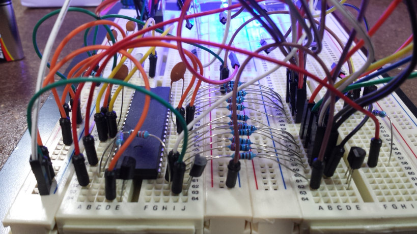
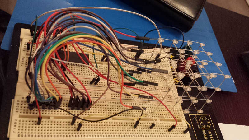
The remainder of the parts only took a few days to arrive so I could get started on the main electronics involved in the build. I chose to test the circuit on a breadboard before soldering the more permanent solution onto Veroboard.
Please note throughout this project I was referring heavily to this Instructable
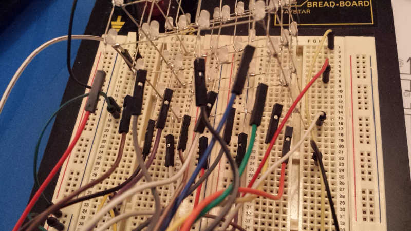
I used female to male connecting wires to connect the 16 wires to the cathodes and 4 male to male connecting wires to the anodes which were attached to the breadboard. The other components were connected in a logical fashion elsewhere on the board.


Programming the ATMega16
In order to properly test the LED Cube, I had to program the AVR which was a major reason I wanted to undertake this particular iteration of an LED cube. I used the manual from Adafruit to guide me through the process.
First I had to download the USBTinyISP driver and AVRDUDE and to test for the correct installation (apart from simply entering avrdude into command prompt), enter command prompt and enter:
avrdude -c usbtiny -p m8
If the following error shows, it proves that avrdude is installed and communicating with the usbtiny, but is not connected to a chip.
avrdude: initialization failed, rc=-1
         Double check connections and try again, or use -F to override
         this check.


avrdude done.  Thank you.
I used the supplied code from the instructable to first test the cube, to make sure I was programming the chip correctly.
All was working correctly on the breadboard, so I’ll leave the big reveal of the working cube to the prettier Perfboard version!