Building an Original i3 MK2 Kit 3D Printer - The Frame
I was actually on holiday in New Zealand when I researched and ordered my 3D printer. I had saved hard for the holiday and towards the end I realised I had more than enough left over to finally buy a printer!
Buying this printer
I had originally intended to source my own parts to make a MendelMax 1.5+ when I began researching printers. This was back in 2012 when I first got into 3D printers and actually built a few Mendels on a volunteer weekend for building printers for schools. I got so far as starting to print my own parts on the printer at the HackerSpace in 2014 before getting distracted with life, uni and everything. So the project was put on hold until 2016!
The Original i3 MK2 had only just been released with the new PEI sheet on the heatbed. This tipped me over the edge and after reading many glowing reviews online I promptly put in my order and began the wait! There was a 3 week lead time when I ordered but I got the shipped and tracking notification only just over a week later. Less than a week after that the printer had arrived - just in time when I’d started back at uni!
The Build
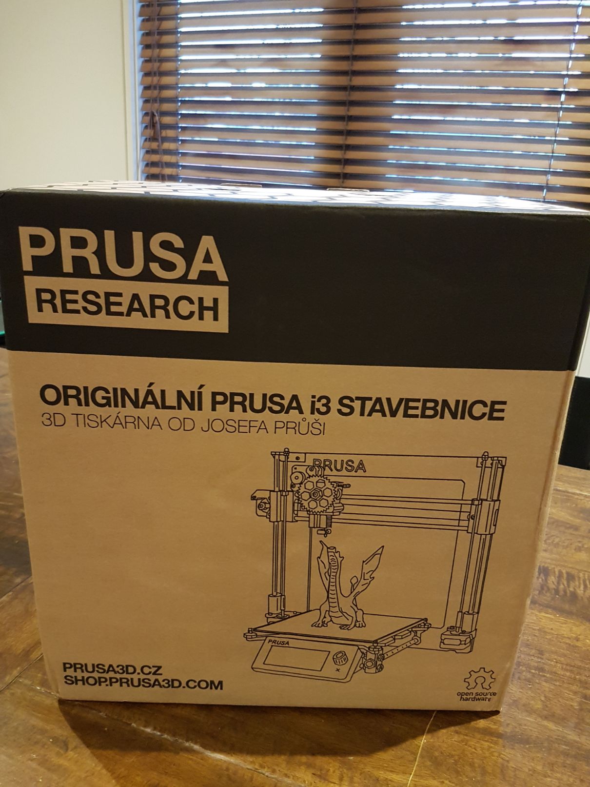
What a good looking box…
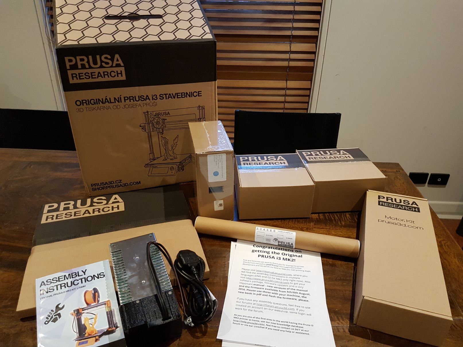
…with boxes in boxes…
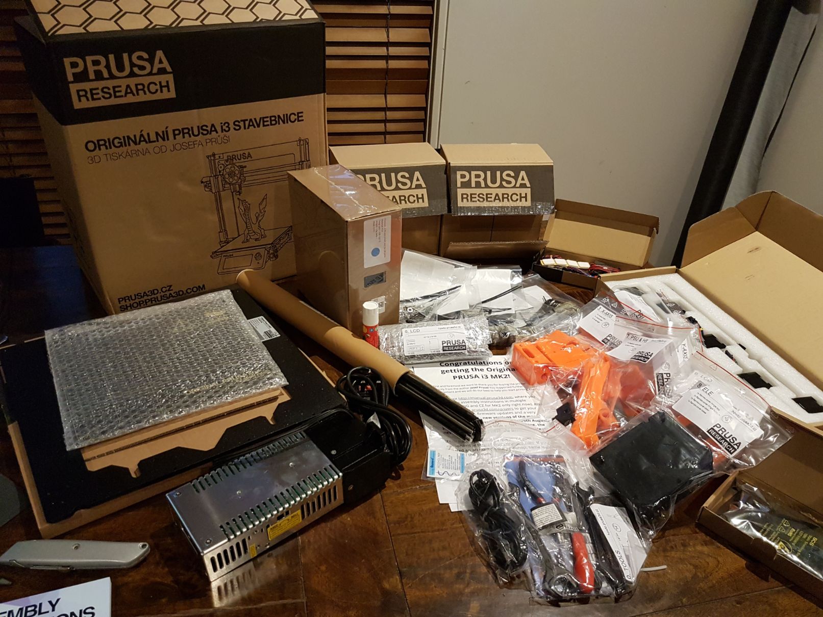
…and bags in boxes!
I took my time with the build; spreading it out over two days for the actual build time. The instructions for this model are really very good and could easily be constructed within a day - I just wanted to take my time so as to minimise mistakes and just enjoy the making process.
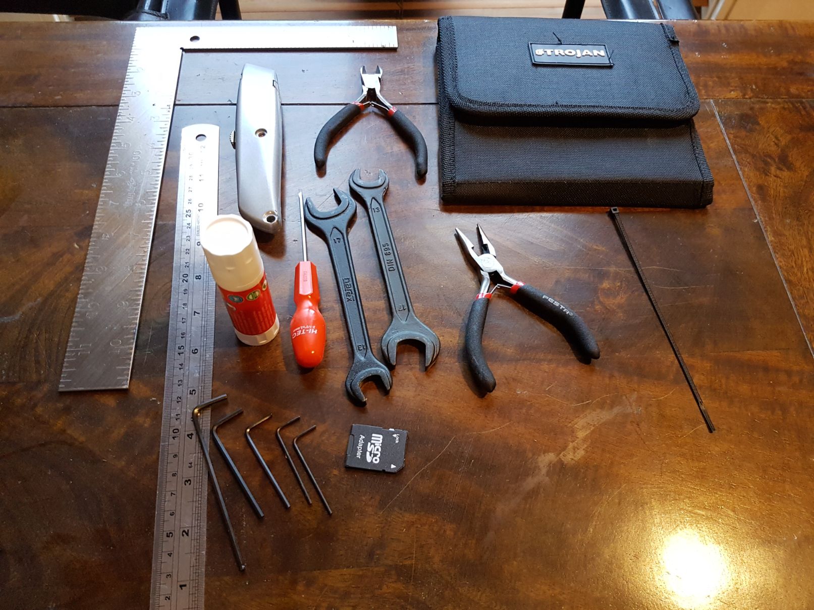
Here are the tools I needed for the build
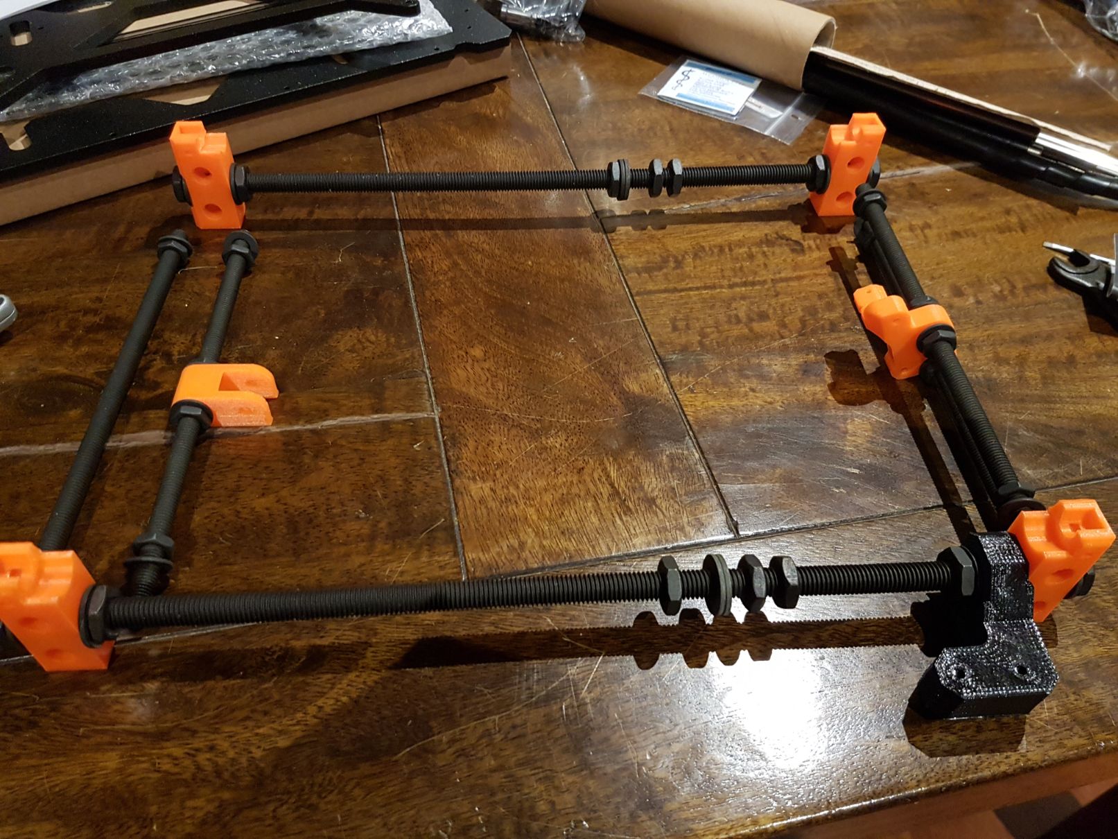
I started with the base which is the Y-axis - in this kit all of the printed parts were orange much to my dismay but it does give a striking contrast with the black.
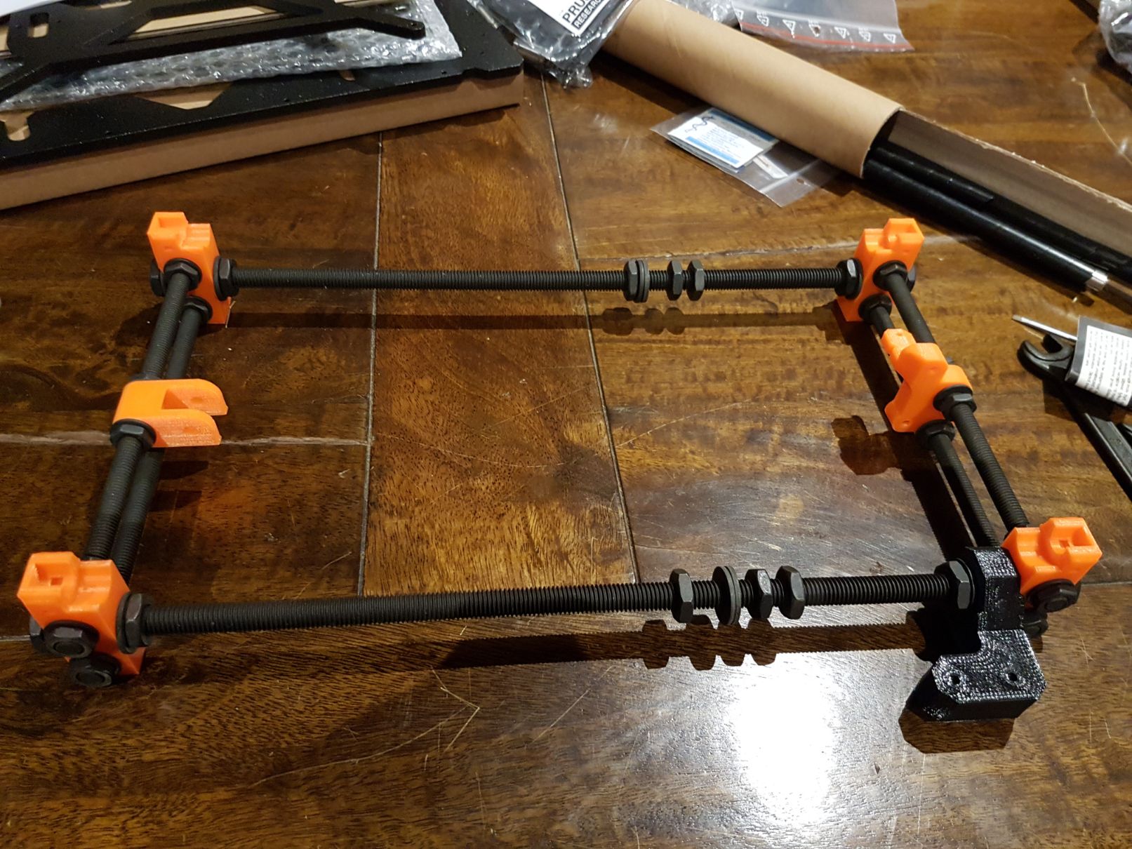
Then I squared up the base as best I could using my set square and the polished rods that the base would run on - I spent a lot of time on this because it makes quite a difference to the final prints.
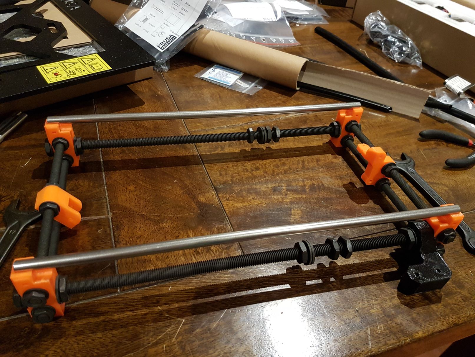
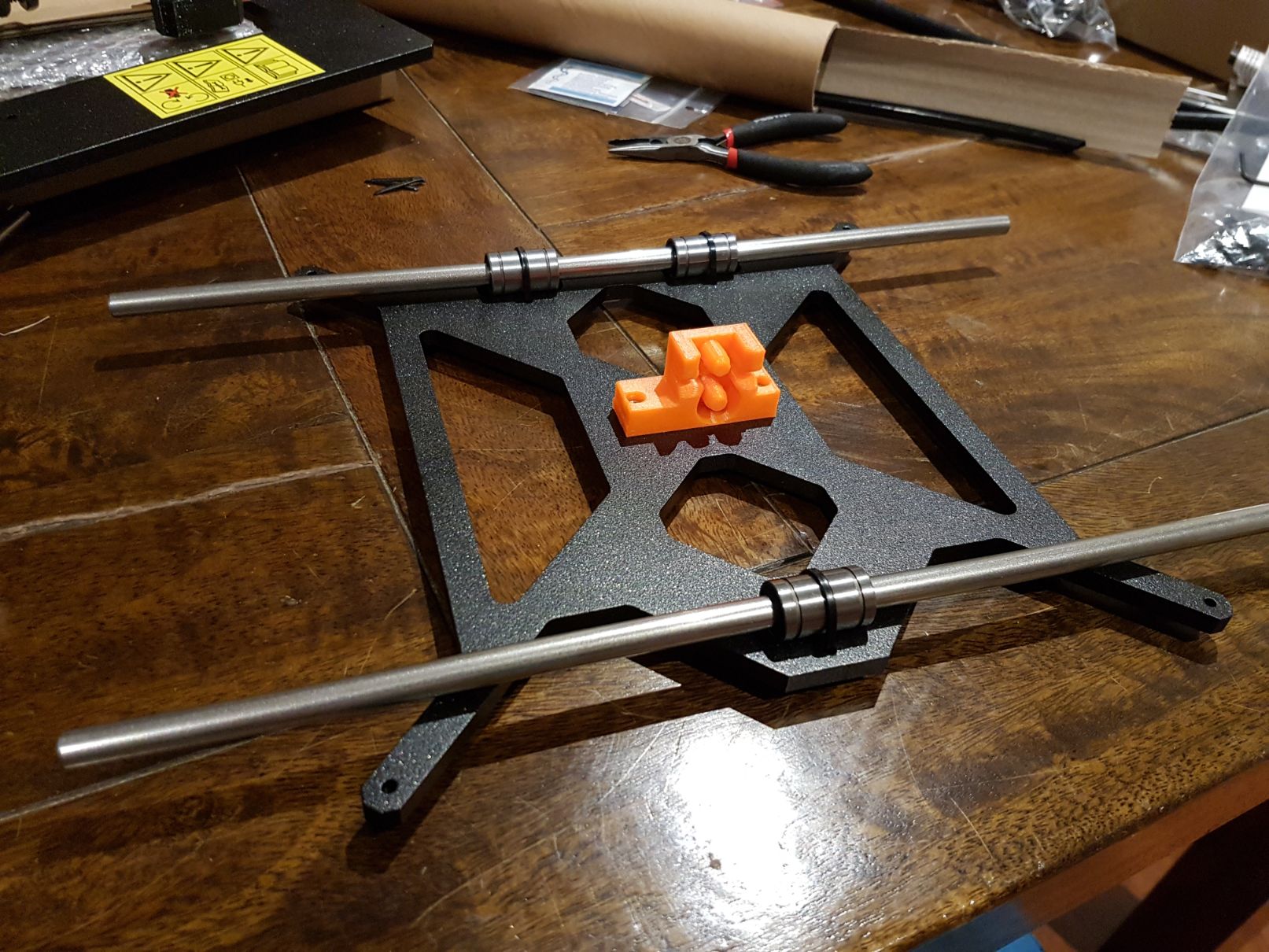
This is how the base connects to the rods using the bearings which are simply zip tied on. The printed part in the centre is what connects to the belt allowing the base to move along the Y-axis.
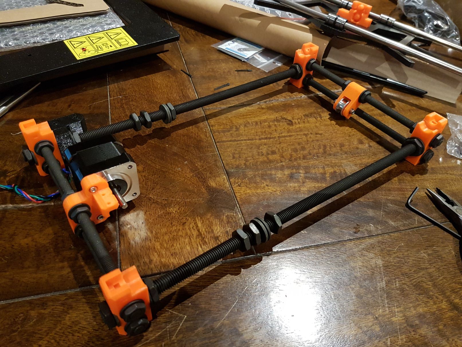
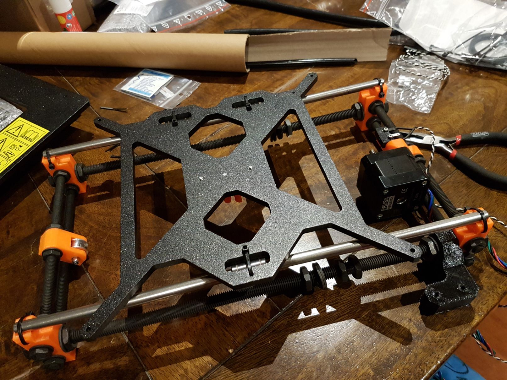
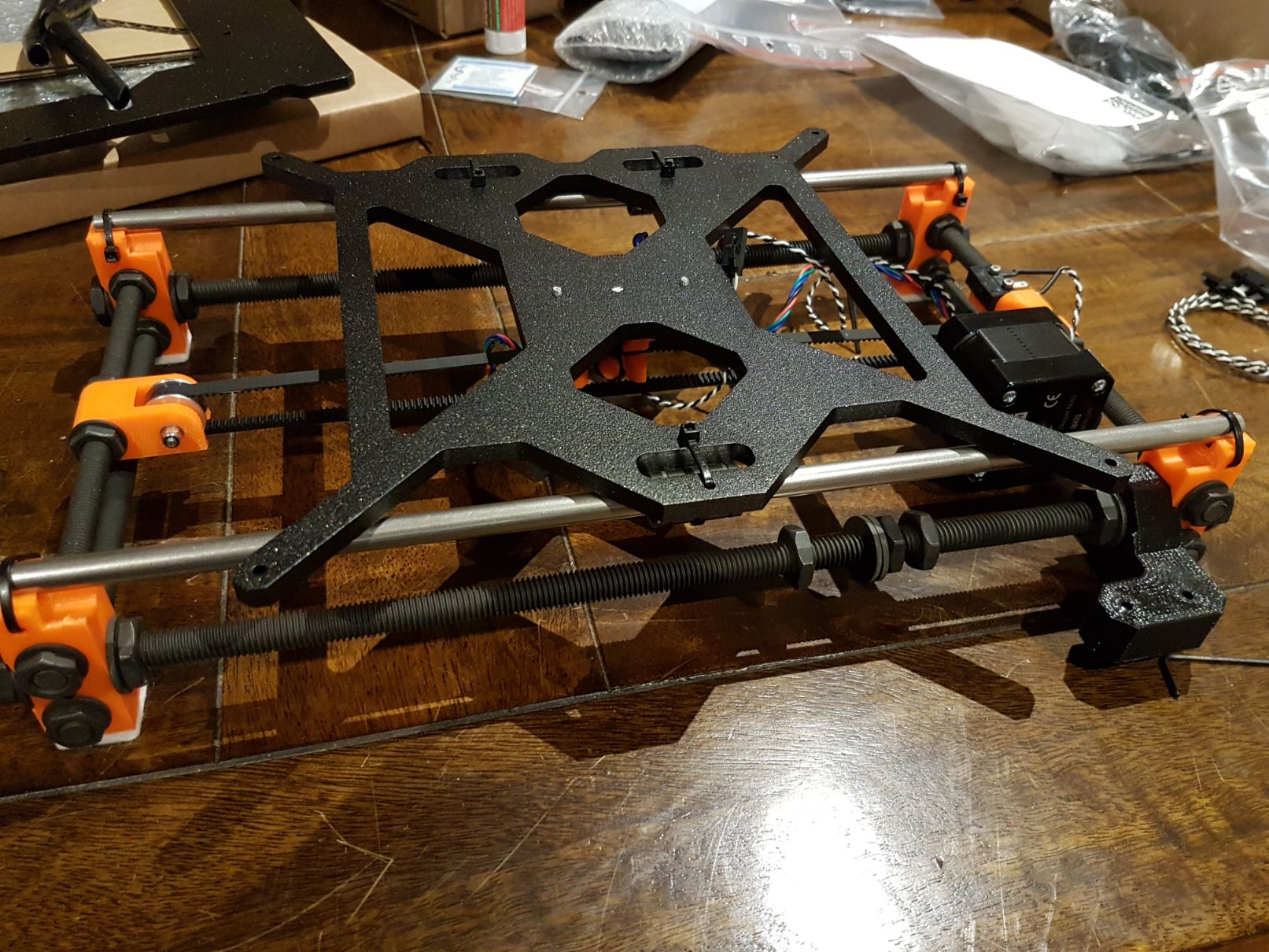
Now mounting the stepper motor on the base before the base is placed on top. Then the belt is connected which is taut but not in tension to allow for accurate movement by the stepper motor.
The next bearings; this time for the X-axis had to be carefully placed in these printed parts, or more accurately ‘shoved in so hard I thought I’d break the damn things.’ If you’re planning on building one of these my best piece of advice would be to print spares especially of these parts.
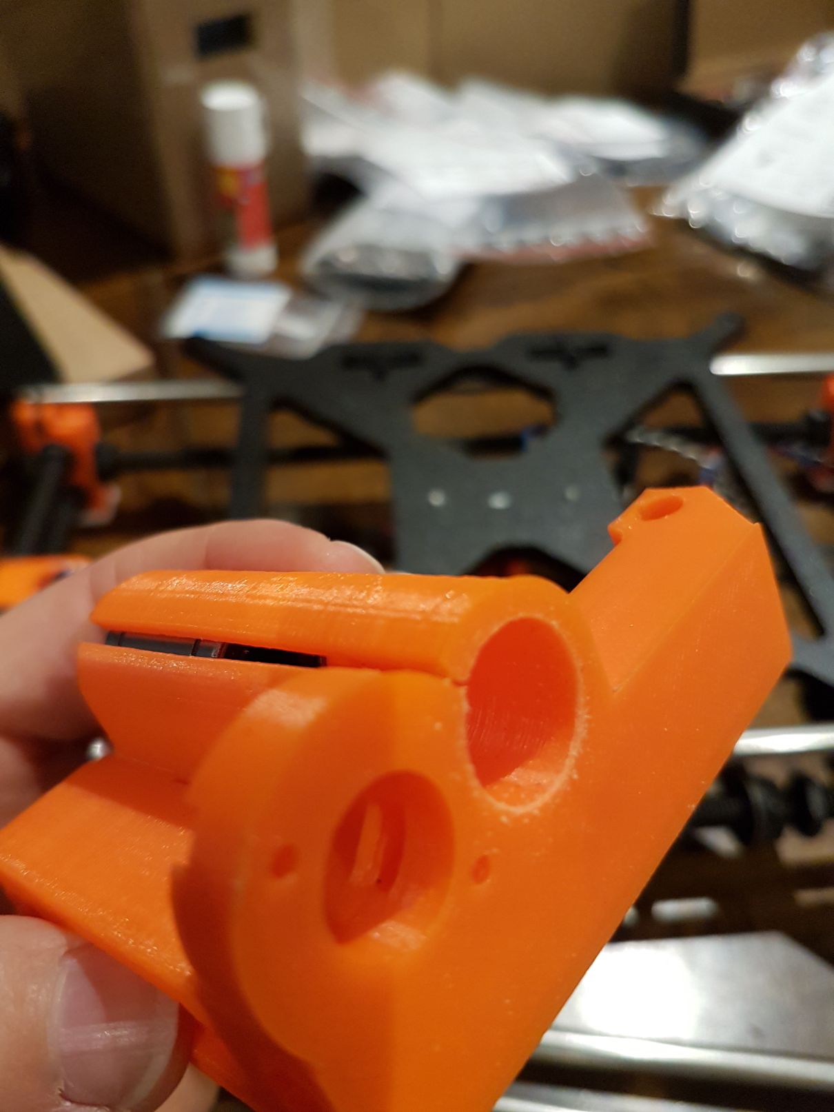
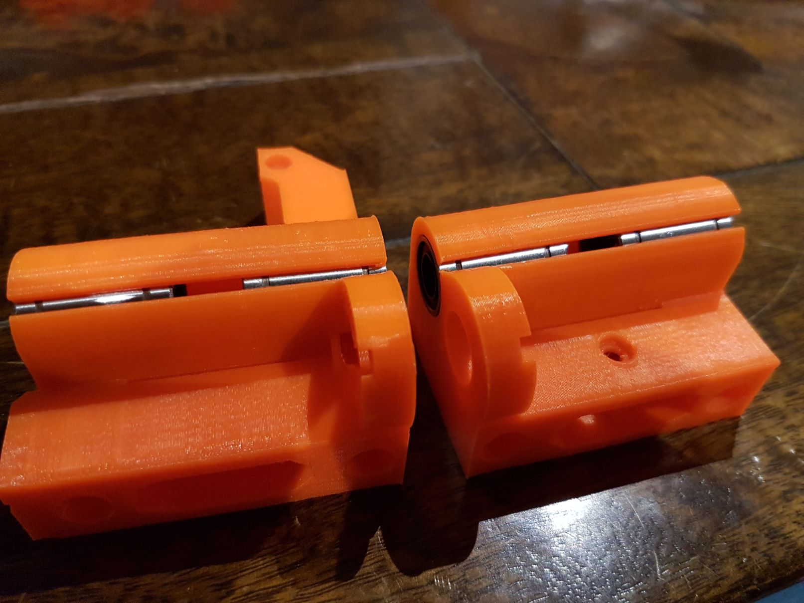

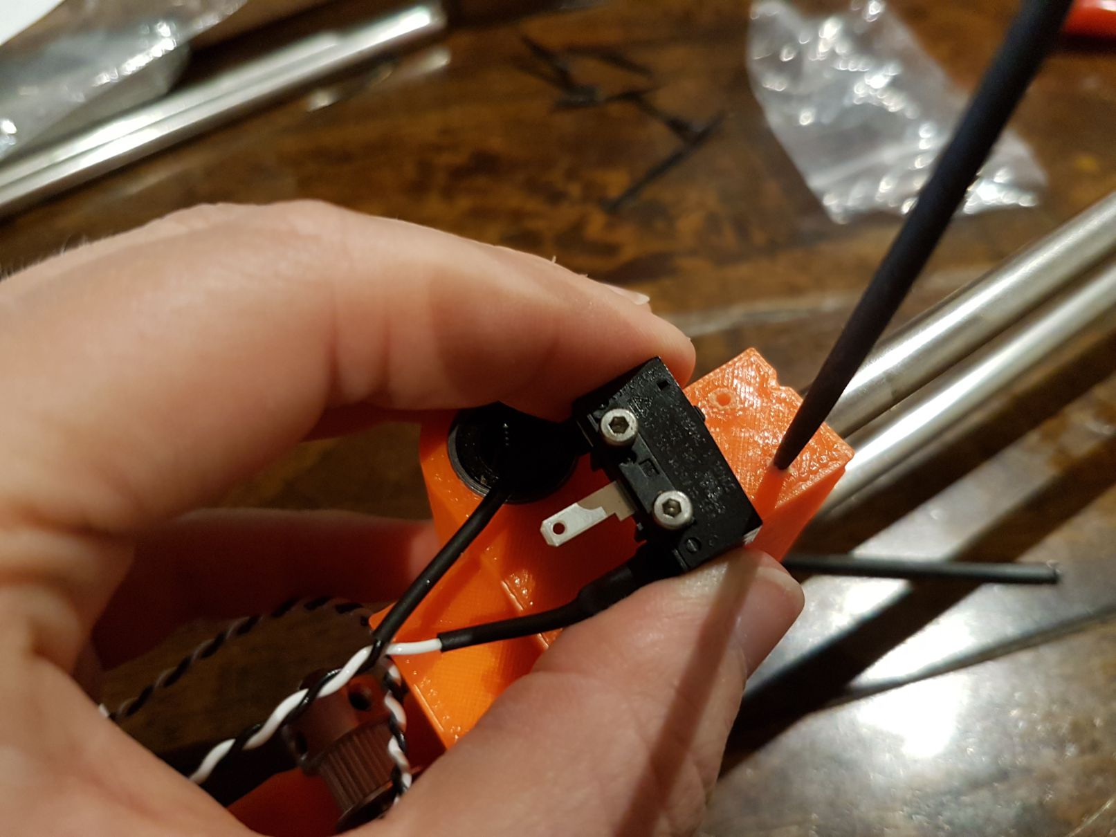
Next I mounted the end stop for the X-axis; this is a simple mechanical switch that is engaged when the extruder on the x-axis moves all the way to one side allowing the printer to zero itself.
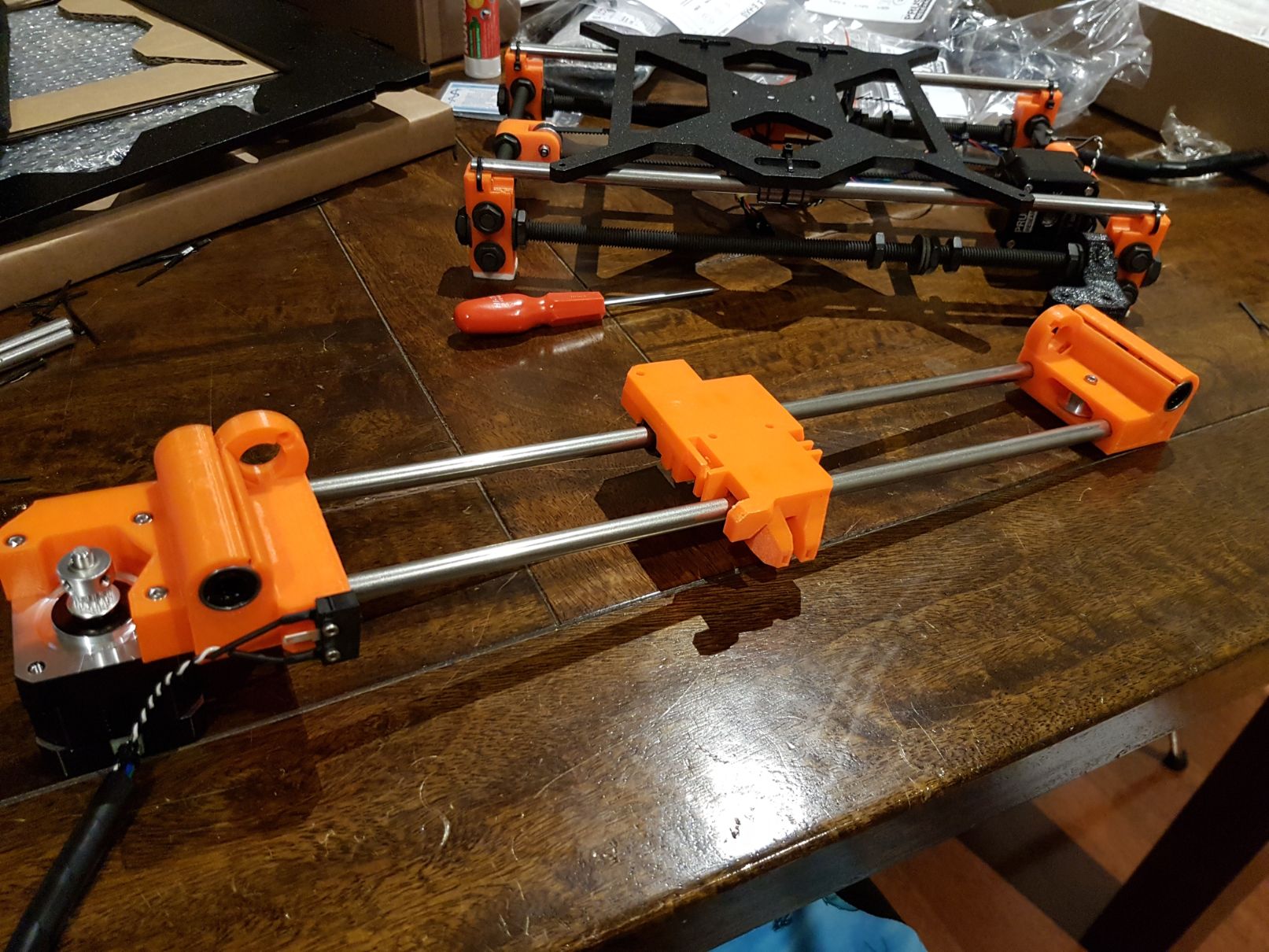
Here is the assembled X-axis ready to attach to the rest.
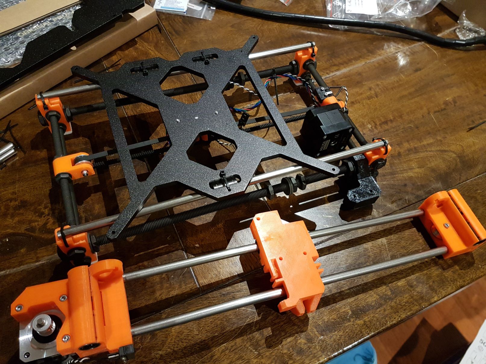
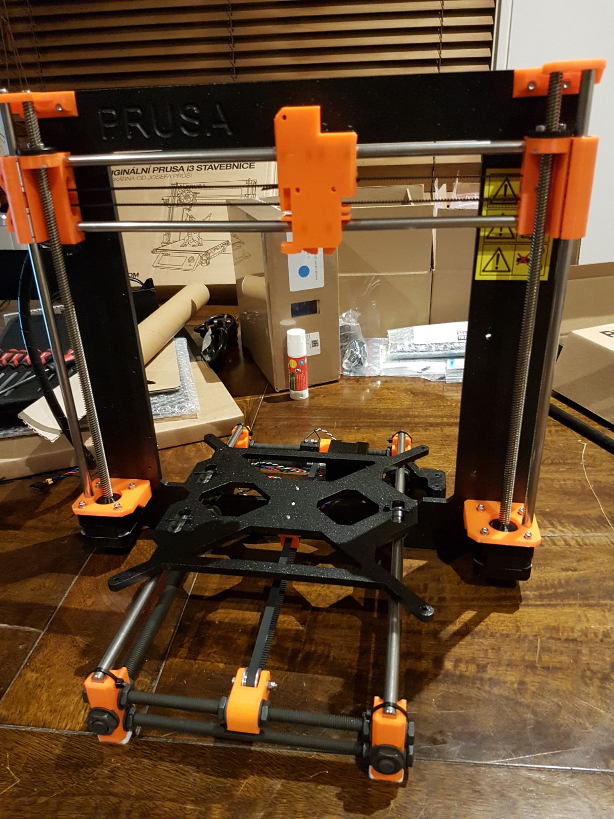
And like magic here is the frame assembled! Sorry I think I got too excited and forgot about the photos in-between but it simply involved screwing a few more printed pieces together and mounting the two stepper motors (which were already attached to the threaded rods) to the aluminium frame.
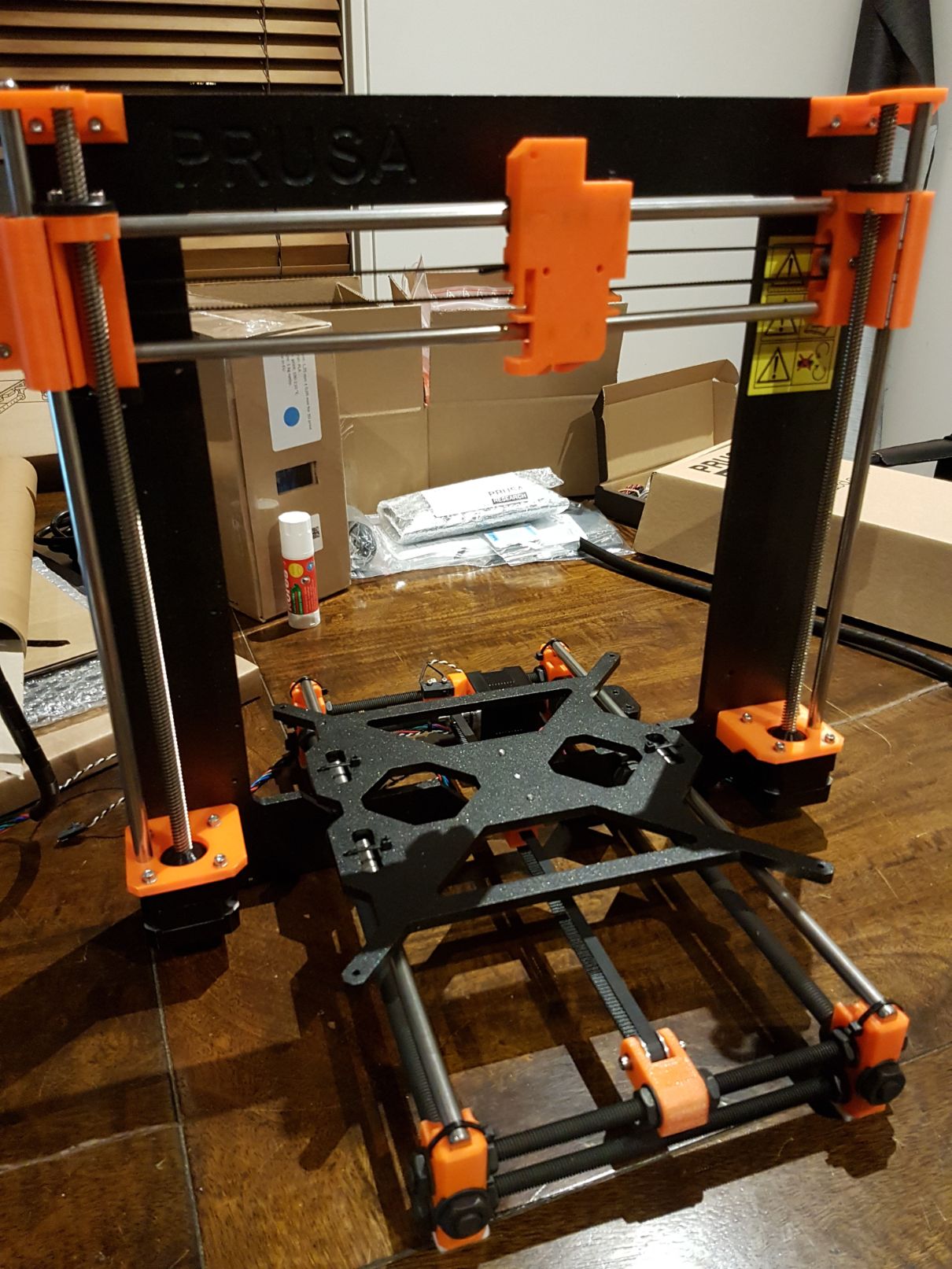

Here is where I left things for the night with the skeleton of the printer complete. Tomorrow will be mounting the extruder and sorting out the spaghetti of the electronics!